Designing an Autocross Course -- A Recap
This page recaps the design of a typical autocross course. I (Jeff Rye) designed this course for the first event of the Minnesota Autosports Club 2018 season. We ran this course on Saturday, April 28, 2018 at Canterbury Park in Shakopee, MN.
Here's the course as driven by me in a 1991 Mazda Miata in the STS class:
In the sections that follow, I recap my design process and discuss some details of the course. Note that I didn't invent this process, I follow in the footsteps of Roger Johnson, relying heavily on the guidance from his course design guide (available at the Houston SCCA web site). At a high level, here's what I did:
- Obtained base map from site.
- Prepared a base map with obstacles.
- Hand-sketched routes through the site.
- Positioned key elements.
- Defined a path connecting the key elements.
- Positioned cones to define elements.
- Set up the course on site.
Throughout the design process, I provided draft course layouts and discussed logistical issues with our site contact. This helped us minimize our impact on other users of the facility (notably, the visitors to the Expo Center).
I also frequently shared draft designs with the event officials (Event Master, Assistant Event Master, Chief of Safety) and some experienced club members. They gave me feedback to improve my design and avoid any safety issues
Preparing a Base Map
The design process started by communicating with the site. Canterbury Park gave us a map of the space we would have available for our event.

I used this to prepare a base map to work from. I used the satellite view from my computer's map software to get an image of the site. I then used image manipulation software to make the image monochrome, lighten it, and adjust its contrast.
Site Visit and Mapping Obstacles
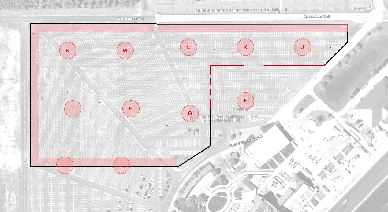
I visited the site with a tape measure and paper copy of this map in hand. I walked the lot taking pictures and making notes, to identify all the obstacles I would need to design around. This lot has numerous light poles in it, so I carefully located each of these on the map. The lot also has several drains. I marked these locations as well. Finally, this lot had (at the time) a line of wood posts separating the Southeast corner (the area marked "Parking for Expo Center") from the rest of the lot.
Back on my computer, I created a file in my favorite vector drawing software, OmniGraffle. While OmniGraffle is not designed for this type of work, with some careful attention to scale I was able to make it work. One of its strengths is that it lets me construct my images from numerous layers. By toggling the visibility of these layers I can do all my work in one file and generate numerous alternate views of the course. Also, since OmniGraffle is a vector-based drawing program, I can easily manipulate individual objects and zoom in/out without loss of readability.
I added the map image to the OmniGraffle file and carefully marked the obstacles. In this base map, I marked drains with small blue circles. I used red circles and rectangles to mark out required safety distances from hard obstacles and the site boundaries.
Stencils
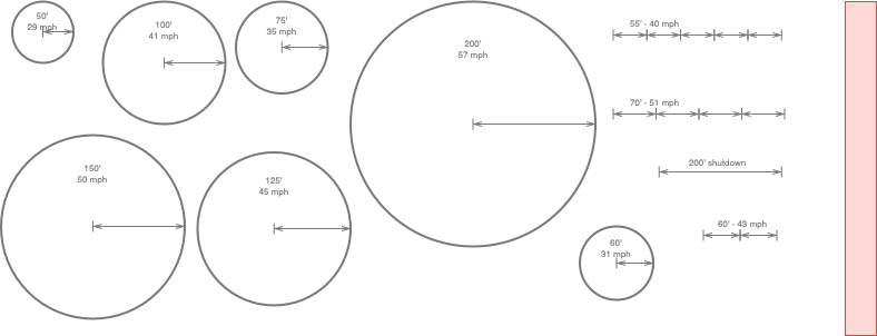
To aid in design, I carefully devised a scale based on some known measurements in the base image. I created a set of to-scale stencils that I could copy and paste into the design without repeatedly measuring items in my drawing software.
These stencils reflect the notional speeds for a vehicle capable of maintaining 1.1g during cornering. Most street cars will be below this limit, so the stencils give a soft upper-bound on the likely speeds to be attained on course. We have a few vehicles capable of exceeding 1.1g, but in our club those vehicles are driven by experienced drivers who can maintain safe control of their vehicle at those higher limits.
I created several circles with varying radii, each labeled with the speed for a car at 1.1g. I also created some slalom measurements, again labeled with the spacing and the theoretical speed limit for a car at 1.1g. I also created a 50' wide red rectangle to use in marking safe run-off areas.
Defining Key Elements
I printed several copies of my scale base map and used a pen to hand-sketch various routes through the site. I do not have any photos of these hand-drawn maps, but they were not works of art.
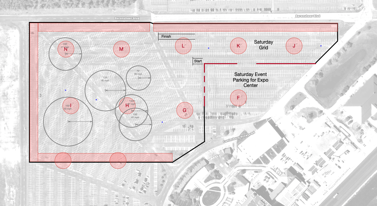
I decided to use the Eastern-most segment of the lot for paddock and grid, leaving a large, mostly rectangular area for the course itself. I decided to lay out the course to run clockwise, and positioned the start and finish areas.
This site has some residences a short distance to the West, so I tried (but did not totally succeed) to keep hard acceleration zones running North/South or toward the West to minimize noise in the direction of these residences. Further, I made sure to route cars around the outside of poles and obstacles. This ensured that if drivers spun, their momentum would carry them away from danger.
Using the paper sketch, I selected some stencils and placed them on the map to work out actual spacing. As I placed these, I chose circles with speeds that flowed together nicely. I wanted to ensure that drivers had to do some speeding up and some slowing down to connect the arcs, but that the speeds were similar enough that drivers could maintain some momentum.
Defining the Path
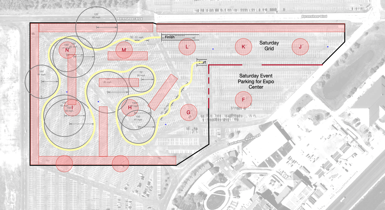
Next, I defined a notional path for cars to follow. I created a sequence of lines with a scale width slightly a bit wider than a normal car. I styled these as Bezier curves and adjusted the points to make the lines smooth and continuous. Since cars make arcs when they turn, I made sure my lines did as well.
This figure shows the benefits of hindsight -- it is the actual path I planned for the course. In practice, I revised the path numerous times and went back and forth between adjusting the path and adjusting the positions and radii for the arcs involved. Also notice that this path includes a 55' (~40mph) slalom near the start of the course and a mini-slalom near the finish.
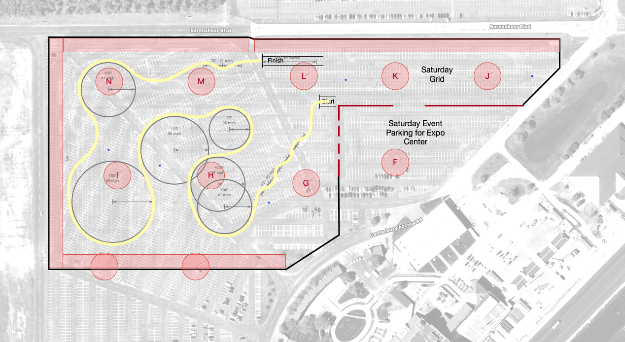
The path above does not quite show the whole picture. When positioning that path, I added more circles to define arcs with speeds that would make sense. These additional arcs were a crucial part of the design, ensuring that cars would operate at their limit of grip and at reasonable speeds.
One of the key principles here was to keep the cars working. I wanted them to always be cornering, or accelerating, or decelerating. I also tried to ensure that cars would not be forced to slow down so much that drivers would feel like they were "parking it". And I avoided situations where cars would just accelerate in a straight line. These subtle parts of the design made the course feel like it "flowed".
Also, while defining the path and spacing, I added additional red boundary zones to ensure that I was leaving adequate space between adjacent parts of the course.
Placing Cones
While it feels like the key part of designing a course, placing the cones to define the elements was the very last step. And, it was largely an anti-climax.
Since I worked hard to define a path that would be challenging and fun to drive, I just needed to position cones to guide cars along that path. The only artistry in this step was choosing elements that would be easy for drivers to see and understand at speed.
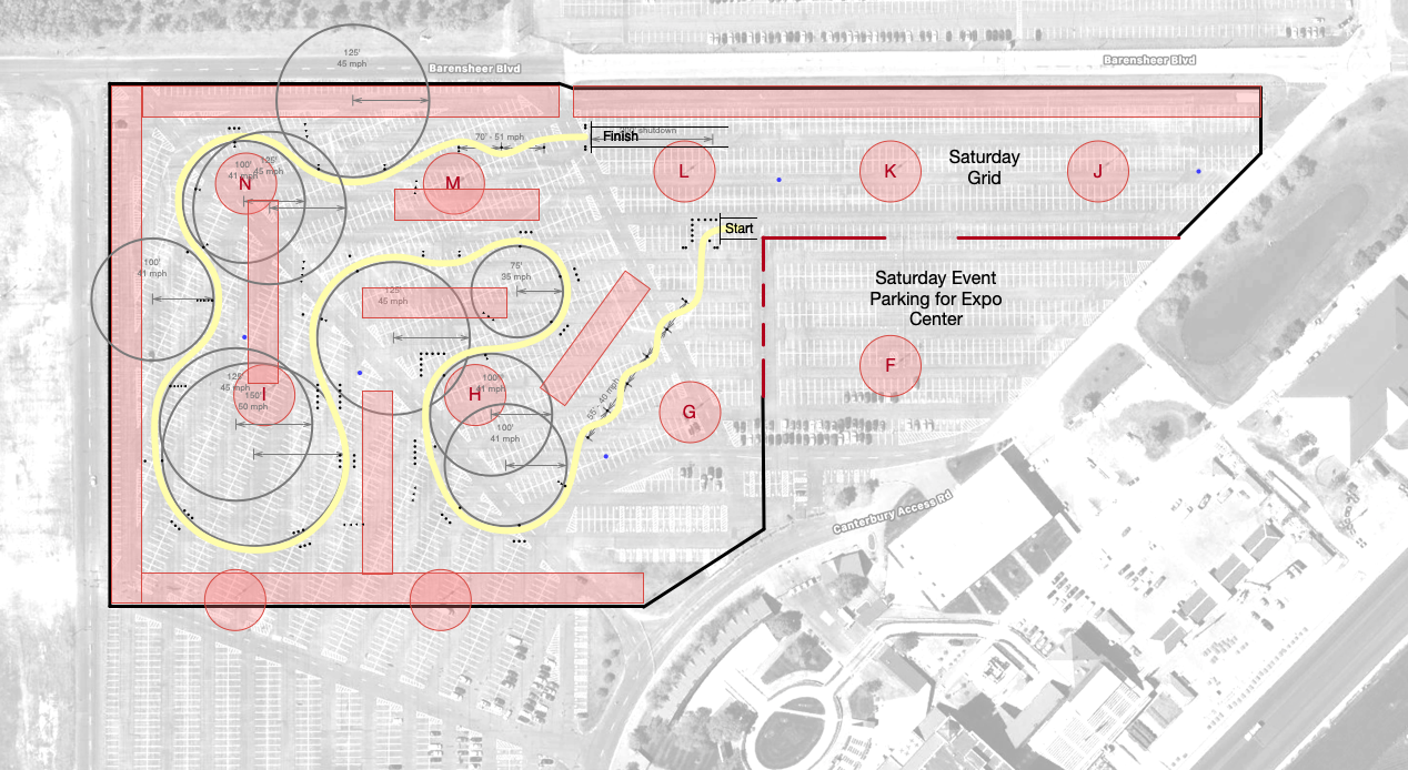
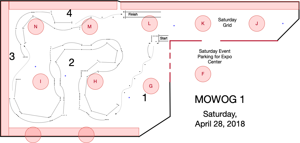
When I originally made this course, I did not create and publish a map for participants prior to the event. However, most times I take the time to do so. For this recap, I revisited the course design and added the additional details to create a publishable version of the course.
In the publishable version of the map, I removed the background and spacing/design aids. This left just the cones. I then added lines to denote where to put down flour. The flour lines are not officially part of the course (drivers can cross those lines without penalty), but they help drivers (especially novices) follow the course and spot upcoming elements.
On the publishable version of the map, I also added dashed lines denoting the route to take around slaloms and offsets. Finally, I labeled the corner stations and added the event name/date.
While this final publishable map is to scale, I warn participants that the actual course may differ in both style and substance, for reasons that will become clear in the next section.
Course Setup
As the course designer, my job did not end with the published drawing. I showed up early (actually the night before for this course) to work with our setup crew to actually construct the course. I brought printed copies of the map wth background and spacing information for each of the setup workers.
During this setup, I had a couple volunteers rough in the elements per the maps. Meanwhile, another volunteer and I walked through the course adjusting the cone positions and fixing visuals. During this setup, I rewalked each element numerous times, looking ahead to ensure that the next element was clearly visible and wasn't confusing. As necessary, I added pointer walls to help guide drivers.
While setting up the course we discovered a drain that I missed when surveying the site. This drain was right in the final element before the finish. I adapted the course by replacing the offset with a mini-slalom and adusting the alignment of the final slalom to control the speed leading to the finish. This final arrangement ended up driving better than the paper design would have.
Lessons Learned
Despite my extensive design and planning, this course suffered from two relatively major problems.
First, I failed to make good accommodations for my corner workers. The workers for corner two ended up being in the middle of the course. They had to constantly watch for cars coming and going on all sides. To fix this, I would have had to choose a different route. In subsequent designs for this site, I have carefully considered course worker locations early in the design and taken care to make their locations safer.
Secondly, this route made us drive over a section of the lot that turned out to be very bumpy. In the video at the start of this write up between 0:30 and 0:34, you can see the car bucking over bumps in the pavement. For street cars with stock suspensions, these bumps were not a big deal. But for prepared cars with stiff suspensions, the bumps caused cars to bounce uncomfortably. In subsequent designs I have taken care to route vehicles around this bumpy area (or cross it in a less jarring direction).